Chicago Electric Battery Charger
Analysis and Schematic: Model 66783
Recently my charger returned from a neighbors house DOA. I took it apart and determined that
the thyristor (Silicon Controlled Rectifier) was blown. My great powers of observation and
analysis led me to observe the hole in the SCR where the chip had exploded blowing away part
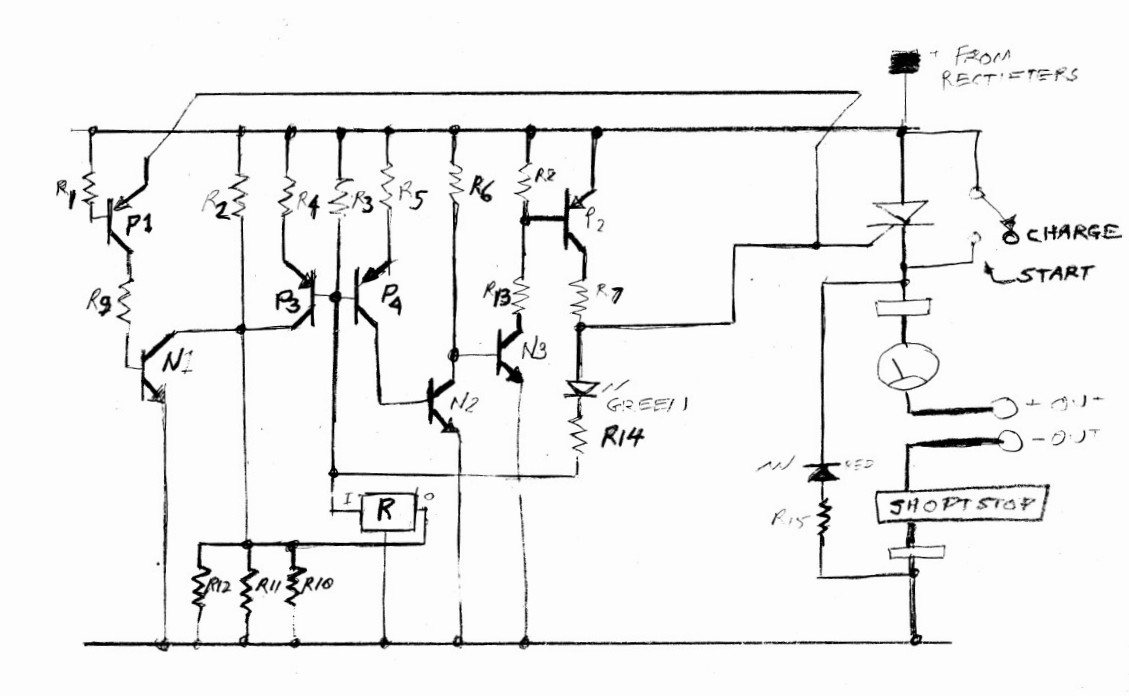
of the plastic cover. I ordered a new thyristor and spare and while waiting decided to reverse
engineer the schematic of the circuit board, since one was not available. Click image for
bigger picture.
 I quit working with hardware about 30 years ago so I am a little rusty, however after
studying the diagram I have come to several conclusions. First, since a thyristor or Silicon
Controlled Rectifier (SCR), is either ON or OFF, and once turned on can only be turned off
by removing the power source, reversing the voltage applied to the SCR or if the current falls
below a certain value, the "holding current". Once the SCR is turned on the only way charging is
interrupted is to turn the charger off, disconnect from the battery or wait for the current to
fall below the holding current. Charging current is a function of the charging voltage, which is
controlled by selecting a position on the "Setting" switch (not shown in the circuit diagram).
If the voltage is too high the holding current will remain above its turnoff threshold. If the
holding current threshold is not reached the battery will continue to charge, resulting in water
loss and possibly damage to the battery. The only thing the circuitry can do is TURN ON the SCR
or not turn it on. It does not monitor the battery voltage, except to turn the SCR on, so all
interruption of charging is controlled by the holding current and if the lower threshold is
not reached the SCR remains on.
I quit working with hardware about 30 years ago so I am a little rusty, however after
studying the diagram I have come to several conclusions. First, since a thyristor or Silicon
Controlled Rectifier (SCR), is either ON or OFF, and once turned on can only be turned off
by removing the power source, reversing the voltage applied to the SCR or if the current falls
below a certain value, the "holding current". Once the SCR is turned on the only way charging is
interrupted is to turn the charger off, disconnect from the battery or wait for the current to
fall below the holding current. Charging current is a function of the charging voltage, which is
controlled by selecting a position on the "Setting" switch (not shown in the circuit diagram).
If the voltage is too high the holding current will remain above its turnoff threshold. If the
holding current threshold is not reached the battery will continue to charge, resulting in water
loss and possibly damage to the battery. The only thing the circuitry can do is TURN ON the SCR
or not turn it on. It does not monitor the battery voltage, except to turn the SCR on, so all
interruption of charging is controlled by the holding current and if the lower threshold is
not reached the SCR remains on.
I have not analyzed the circuitry for the float condition so I am not sure how effective the charger would be as a float charger, but since the circuitry does NOT monitor the battery voltage after being turned on, but relies on the action of the holding current I am not comfortable with the unit as a float charger (more like a Bloat Charger).
Note that for the diagram the component labelled "R" is drawn as a three terminal regulator because neither NPN or PNP transistors made sense in the schematic. One never turned on and one never turned off.
Also, note that the "charge/Start" function switch simply shorts the anode/cathode of the SCR, effectively bypassing the SCR. I checked output voltages for the various charger settings and found, not surprisingly, that the lowest voltage was for "6 V 10A Fast Charge" and the highest voltage was for the "12 V 55 A Engine Start". Since the SCR is rated at 55 amps that may be where the 55 amps figure comes from BUT since the SCR is bypassed in the "start" mode the figure seems meaningless.
I know that if I ever blow another SCR (I ordered a spare) until I replace it I will regain charging by just changing the "charge/Start" function switch to "start" and knowing that the output voltage will be a couple volts higher (two diode drops ~= 1.4 volts for the SCR) I will need to carefully monitor the battery heat buildup and fluid loss.
This information is presented without any guarantee or warranty. Use it at your own risk. If you damage anything, either the charger or a battery or even yourself you are on your own.
msanderz